After getting the chassis in the garage, it’s surprising how small it is, it’s also fairly light. The newly modified chassis from Chesil has new floor pans and new framehead.
Leaving aside the dust, Chesil seems to have done a good job of the work, as well as sandblasting and painting and it looks like new.
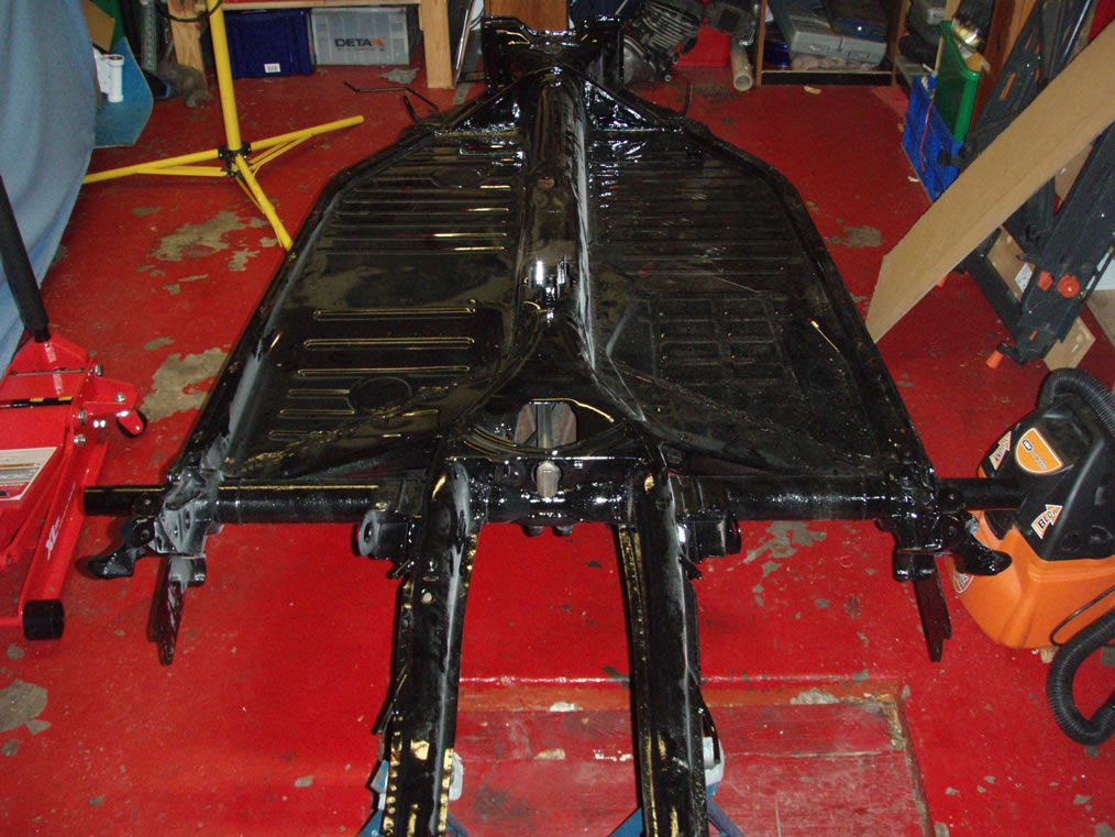
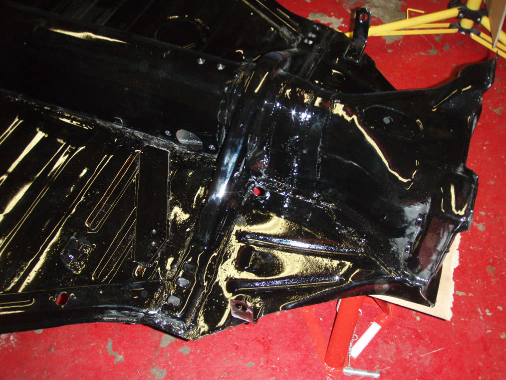
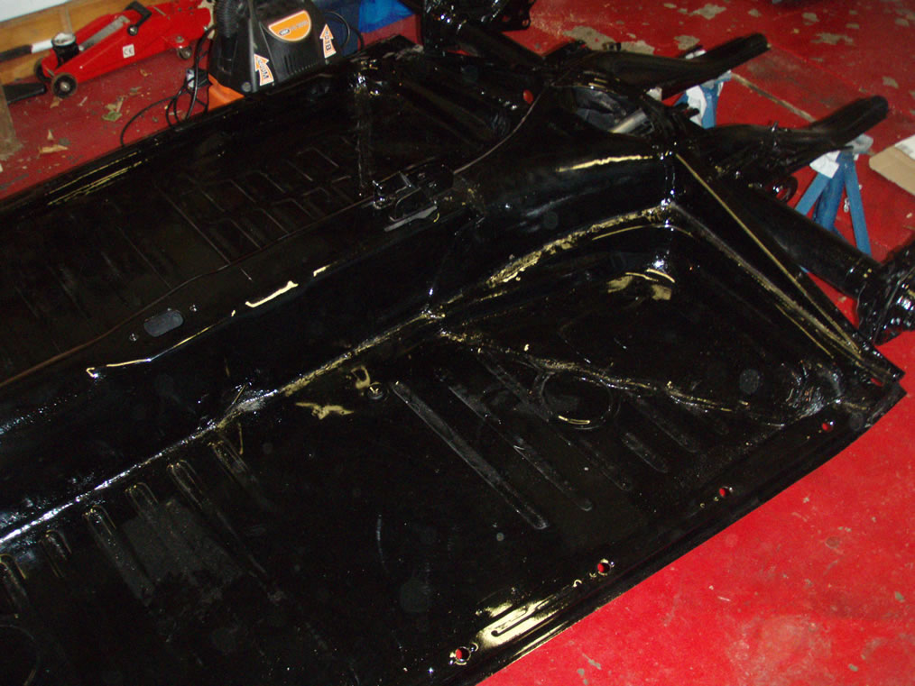
March 2010
We thought about applying a coat of Rubbercote (a flexible setting rubber) on the underside of the car but were dissuaded by the company that produce the product because it would likely fall off.
Instead, we added two more coats of Hammerite to the underside of the chassis. It won’t be driven in the rain/wet, but given the English weather it made sense to add a bit more protection.
April 2010
The next job was to take the rear suspension apart. The car has independent rear suspension which uses a spring plate and torsion arm assembly. Chesil advised taking it apart to grease the splines of the torsion arms although I plan to replace everything with new parts, including new torsion arms, adjustable spring plates, grommets and new spring plate covers. As it happened once removed the spring plates and torsion arms appear to be in excellent condtion, the splines shown no signs of wear or corrosion but the rubber bushings were in pretty bad condition.
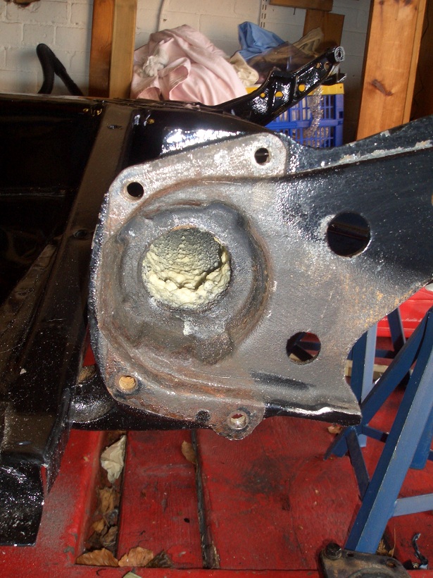
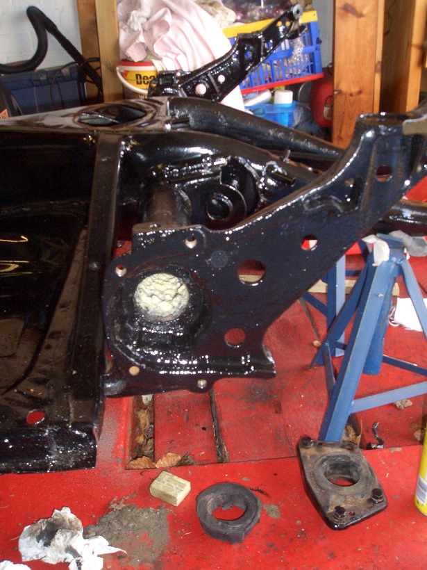
To remove the spring plate/torsion arm you first remove the spring plate cover as shown below. Once removed it is advisable to place a floor jack underneath the spring plate because it is under a lot of tension and is resting on a narrow ledge, one false move (like walking into it) and it may fall off the ledge and hit your shin/foot/face if you’re a midget. We then sprayed a LOT of WD40 between the plate and the chassis as it looked rather solid.
With the jack placed safely underneath the spring plate you then pry the spring plate off the ledge – we used a medium sized pry bar. The Haynes manual refers to this arm flying down potentially off taking various limbs with it, but it dropped down about an inch or so with an uneventful thud. We wedged the pry bar in from the rear of the chassis – to the right of the photos below – to force the spring plate off the ledge.
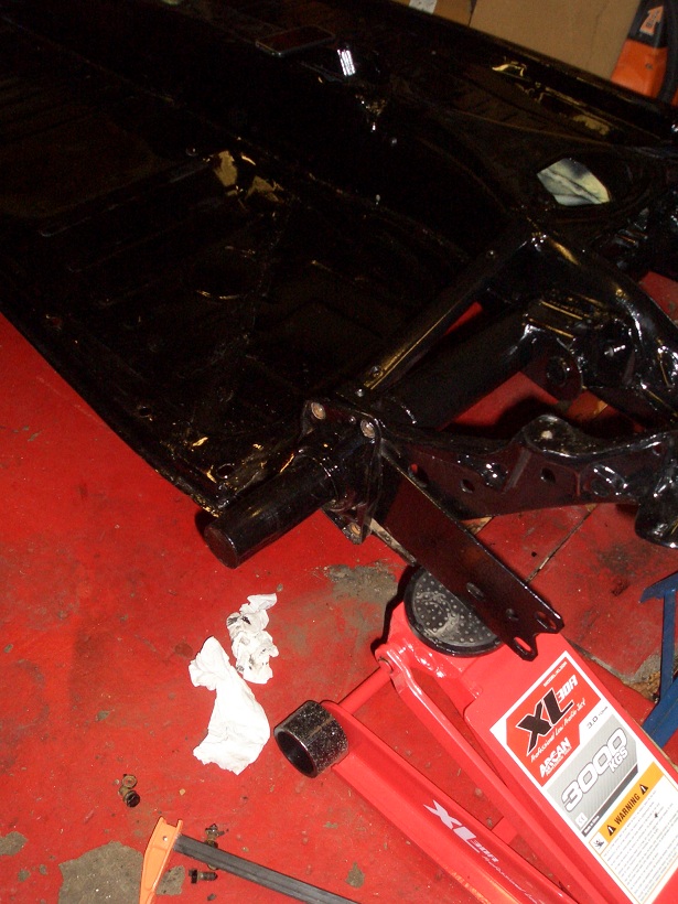
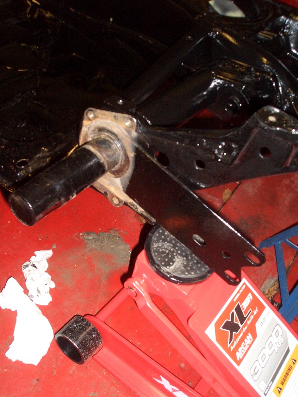
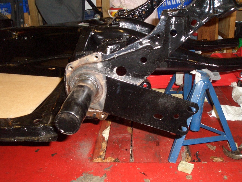
Once in the dropped position it was just a matter of pulling the spring plate out (as shown below). If we were reusing this torsion arm and spring plate it would be necessary to either mark the angle of the spring plate in relation to the chassis or to rest an angle finder on the spring plate so you know the standard position of the suspension (and therefore standard ride height) when you go to refit the torsion arms. We are replacing all parts so didn’t need to do this, at any rate both sides were completely different anyway – the Haynes manual will be used to set them at the correct height.
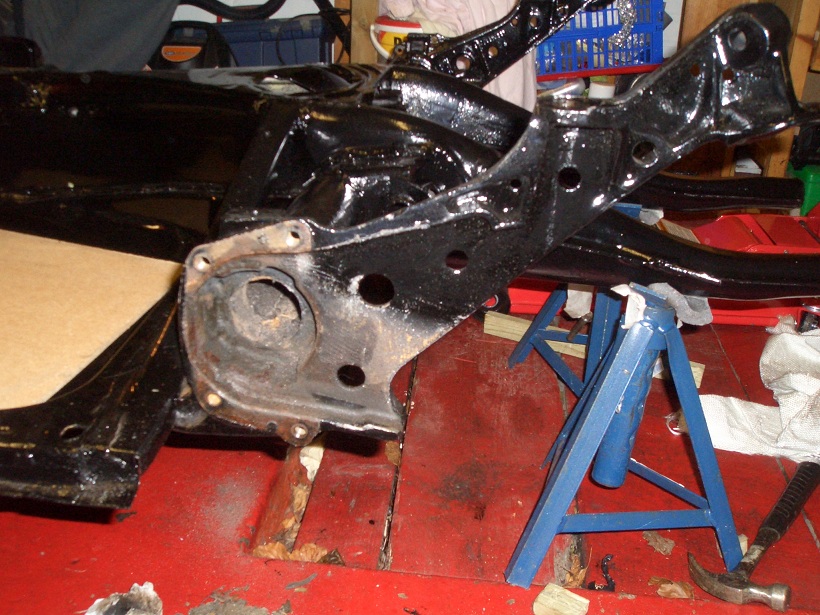
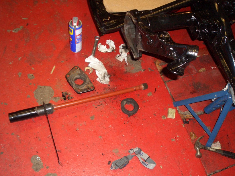
Today we were able to finish a few other small jobs. Firstly was to Waxoyl and paint the torsion arm/spring plate area on the rear suspension. Because the spring plate was in place when Chesil sprayed the chassis this area had not been painted. We used smooth black Hammerite. We also touched up some areas that had been chipped when removing the spring plate. The same was done on the other side of the chassis.
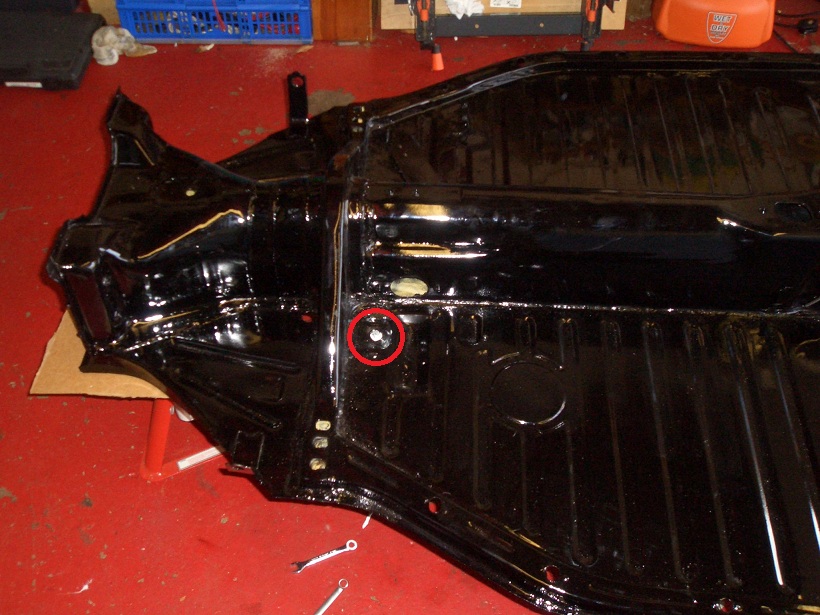
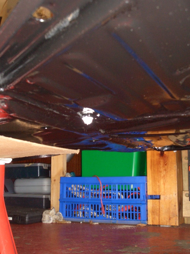
Chesil replaced the old chassis’ floor pans with new versions. However, the floor pans they used were left hand drive and as a result there is a hole in the floorpan at the front of [what is now] the passenger side of the car, this is where the pedal stop bolt would go for the brake/clutch pedal. To close this hole we covered it in flexible, waterproof sealant and placed a bolt the same diameter as the hole through it (also covered in sealant), we tightened this up and will paint it with smooth Hammerite for extra protection.
24 April 2010
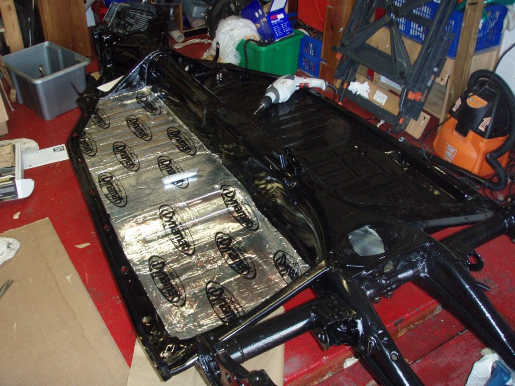
Took the opportunity to begin the sound-deadening of the car. I used Dynamat Xtreme. The difference between the panel with and without the matting is noticeable, it now makes a dull thudding and feels much more solid. I plan to do the entire chassis. The bulk pack should leave enough to do the chassis, doors, bonnet and boot.
The Dynamat was very easy to install and handily was pretty much exactly the right width for the chassis floor. After cleaning the chassis I lay the mat on the floor andpushed it into all the edges, creasing it so it was easy to then cut. I used strong scissors and a stanley knife. After laying it I used a small wooden roller (from B&Q) to ensure it adhered to the chassis properly.
To next section: Brakes & Fuel Lines.